![[Return to Physics Homepage]](../../physics.gif)
![[Return to Mike Coombes' Homepage]](../../coombes.gif)
![[Return to List of Handouts]](../../handouts.gif)
![[Return to Problem Sets]](../../problems.gif)
![[Return to List of Solutions]](../../solutions.gif)
| Questions: | 1 | 2 | 3 | 4 | 5 | 6 | 7 | 8 | 9 | 10 | 11 | 12 | 13 | 14 | 15 | 16 | 17 | 18 | 19 | 20 |
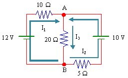
There are three branches, so we will have three unknown currents as shown above. There are two loops with no interior branches, so we will get two voltage equations. The final equation comes from writing a current equation at one of the nodes, point A or B above.
|
12 – 10I1 – 20I3 |
= |
0 |
(1) |
|
10 – 20I3 – 5I2 |
= |
0 |
(2) |
|
I1 + I2 |
= |
I3 |
(3) |
Bringing the constants to one side, we have a system of equations to solve.
|
I1 |
I2 |
I3 |
|
|
10 |
0 |
20 |
12 |
|
0 |
5 |
20 |
10 |
|
1 |
1 |
–1 |
0 |
From a spreadsheet, or any other method, we find
|
Resistor |
Current |
Direction |
|
10 Ω |
I1 = 2/7 A |
→ |
|
20 Ω |
I3 = 16/35 A |
↓ |
|
5 Ω |
I2 = 6/35 A |
→ |
The power supplied by the batteries is Pin = 12 V × 2/7 A + 10 V × 6/35 A = 36/7 W.
The Joule heating of the resistors is
Pout = (2/7 A)2(10 Ω) + (16/35 A)2(20 Ω) + (6/35 A)2(5 Ω) = 36/7 W.
So Pin = Pout confirming the correctness of our solution.
![[Return to Top of Page]](../../top.gif)
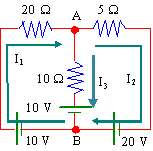
There are three branches, so we will have three unknown currents as shown above. There are two loops with no interior branches, so we will get two voltage equations. The final equation comes from writing a current equation at one of the nodes, point A or B above.
|
10 – 20I1 – 10I3 – 10 |
= |
0 |
(1) |
|
– 5I2 + 20 + 10 + 10I3 |
= |
0 |
(2) |
|
I1 |
= |
I2 + I3 |
(3) |
Bringing the constants to one side, we have a system of equations to solve.
|
I1 |
I2 |
I3 |
|
|
20 |
0 |
10 |
0 |
|
0 |
5 |
–10 |
30 |
|
1 |
–1 |
–1 |
0 |
From a spreadsheet, or any other method, we find
|
Current |
Direction |
|
|
20 Ω |
I1 = 6/7 A |
→ |
|
10 Ω |
I3 = –12/7 A |
↑ (guessed wrong) |
|
5 Ω |
I2 = 18/7 A |
→ |
Since I3 is negative, the true direction is reversed to that shown in the diagram.
The power supplied by the batteries is
Pin = 10 V × 6/7 A + 10 V × 12/7 A + 20 V × 18/7 A = 540/7 W .
The Joule heating of the resistors is
Pout = (6/7 A)2(20 Ω) + (12/7 A)2(10 Ω) + (18/7 A)2(5 Ω) = 540/7 W.
So Pin = Pout confirming the correctness of our solution.
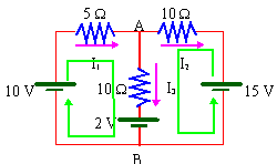
There are three branches, so we will have three unknown currents as shown above. There are two loops with no interior branches, so we will get two voltage equations. The final equation comes from writing a current equation at one of the nodes, point A or B above.
| 10 – 5I1 – 10I3 – 2 | = 0 | (1) |
| 15 + 10I2 – 10I3 – 2 | = 0 | (2) |
| I1 | = I2 + I3 | (3) |
Bringing the constants to one side, we have a system of equations to solve.
|
I1 |
I2 |
I3 |
|
|
5 |
0 |
10 |
8 |
|
0 |
–10 |
10 |
13 |
|
1 |
–1 |
–1 |
0 |
From a spreadsheet, or any other method, we find
|
Resistor |
Current |
Direction |
|
5 Ω |
I1 = 6/40 A |
↑ |
|
10 Ω |
I3 = 29/40 A |
↑ |
|
10 Ω; |
I2 = –23/40 A |
← (guessed wrong) |
Since I2 is negative, the true direction is reversed to that shown in the diagram.
The power supplied by the batteries is
Pin = 10 V × 6/40 A + 15 V ×23/40 A − 2 V × 29/40 A = 347/40 W .
Note that the 10 V and 15 V batteries supply energy to the circuit while the 2 V battery is charging or taking energy out of the circuit (hence the minus sign above).
The Joule heating of the resistors is
Pout = (6/40 A)2(5 Ω) + (23/40 A)2(10 Ω) + 29/40 A)2(10 Ω) = 347/40 W.
So Pin = Pout confirming the correctness of our solution.
We can find VAB by following any of several paths
| VAB | = 10I3 + 2 | = 37/4 Volts |
| = 10I2 + 15 | = 37/4 Volts | |
| = –5I1 + 10 | = 37/4 Volts |
Point A is 37/4 Volts above point B.
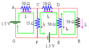
We have four nodes, C, D, E, and F above. We assign a current of arbitrary direction to each branch as shown in the diagram above. There are six branches and therefore six unknown currents, so we need six equations. There are three loops with no interior branches which will yield three voltage equations. For the other three equations, we apply the current law to three of the nodes as shown below.
|
(C) |
I1 |
= |
I2 + I3 |
(1) |
|
(D) |
I2 |
= |
I4 + I5 |
(2) |
|
(E) |
I4 + I5 |
= |
I6 |
(3) |
For the three loops, we get
|
1.5 – 50I1 – 15I3 |
= 0 |
(4) |
|
1.5 + 56I4 + 10I2 – 15I3 |
= 0 |
(5) |
|
–56I5 + 56I4 |
= 0 |
(6) |
Bringing the constants to one side, we have a system of six equations to solve.
|
I1 |
I2 |
I3 |
I4 |
I5 |
I6 |
|
|
1 |
–1 |
–1 |
0 |
0 |
0 |
0 |
|
0 |
1 |
0 |
–1 |
–1 |
0 |
0 |
|
0 |
0 |
0 |
1 |
1 |
–1 |
0 |
|
50 |
0 |
15 |
0 |
0 |
0 |
1.5 |
|
0 |
10 |
–15 |
56 |
0 |
0 |
–1.5 |
|
0 |
0 |
0 |
56 |
–56 |
0 |
0 |
We find
|
Resistor |
Current |
Direction |
|
50 Ω |
I1 = 57/3220 A |
→ |
|
10 Ω |
I2 = –15/644 A |
← (guessed wrong) |
|
15 Ω |
I3 = 33/805 A |
↓ |
|
56 Ω |
I4 = –15/1288 A |
↑ (guessed wrong) |
|
56 Ω |
I5 = –15/1288 A |
↑ (guessed wrong) |
|
none |
I6 = –15/644 A |
→ (guessed wrong) |
The power supplied by the batteries is
Pin = 1.5 V × 57/3220 A + 1.5 V × 15/644 A = 198/3220 W.
Note that the direction of I6 is actually in the direction opposite to shown and thus the bottom battery supplies energy to the circuit.
The Joule heating of the resistors is
Pout = (57/3220)2(50) + (15/644)2(10) + (33/805)2(15) + (15/1288)2(56 + 56) = 198/3220 W.
So Pin = Pout confirming the correctness of our solution.
We can find VAB by following any of several paths but it is easiest to follow AGFEB
VAB = 1.5 V − 1.5 V = 0 V.
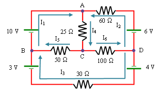
We have four nodes, A, B, C, and D above. We assign a current of arbitrary direction to each branch as shown in the diagram above. There are six branches and therefore six unknown currents, so we need six equations. There are three loops with no interior branches which will yield three voltage equations. For the other three equations, we apply the current law to three of the nodes as shown below.
|
(A) |
I1 + I2 = |
I4 |
(1) |
|
(B) |
I3 + I5 = |
I1 |
(2) |
|
(C) |
I4 = |
I5 + I6 |
(3) |
For the three loops, we get
|
10 – 25I4 – 50I5 |
= 0 |
(4) |
|
6 – 60I2 – 25I4 – 100I6 |
= 0 |
(5) |
|
4 – 30I3 + 3 + 50I5 – 100I6 |
= 0 |
(6) |
Bringing the constants to one side, we have a system of six equations to solve.
|
I1 |
I2 |
I3 |
I4 |
I5 |
I6 |
|
|
1 |
1 |
0 |
–1 |
0 |
0 |
0 |
|
–1 |
0 |
1 |
0 |
1 |
0 |
0 |
|
0 |
0 |
0 |
1 |
–1 |
–1 |
0 |
|
0 |
0 |
0 |
25 |
50 |
0 |
10 |
|
0 |
60 |
0 |
25 |
0 |
100 |
6 |
|
0 |
0 |
30 |
0 |
–50 |
100 |
7 |
We find
|
Resistor |
Current |
Direction |
|
none |
I1 = 1033/3690 A |
As shown |
|
60 Ω |
I2 = –361/3690 A |
→ (guessed wrong) |
|
30 Ω |
I3 = 631/3690 A |
← |
|
25 Ω |
I4 = 672/3690 A |
↓ |
|
50 Ω |
I5 = 402/3690 A |
← |
|
100 Ω |
I6 = 270/3690 A |
→ |
The power supplied by the batteries is
Pin = 10 V × 1033/3690 A – 6 V × 361/3690 A + (3 V + 4 V) × 631/3690 A = 12581/3690 W.
Note that the direction of I2 is actually in the direction opposite to shown and thus the 6 V battery is being charged.
The Joule heating of the resistors is
Pout = (361/3690)2(60) + (631/3690)2(30) + (672/3690)2(25) + (402/3690)2(50) + (270/3690)2(100)
= 12581/3690 W.
So Pin = Pout confirming the correctness of our solution.
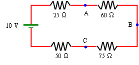
Since the resistors are all in series we can use Ohm's Law to find the current. I = (10 V) / (25Ω + 60Ω + 75Ω + 50Ω) = 1/21 A.
VA = 10 V − (25Ω)I = 8.810 V.
VB = 10 V − (25Ω)I − (60Ω)I = 5.953 V.
VC = 10 V − (25Ω)I − (60Ω)I − (75Ω)I = 2.381 V.
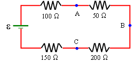
Since the resistors are all in series we can use Ohm's Law to find the current. I = ε / (100Ω + 50Ω + 200Ω + 150Ω) = ε / 500Ω.
We are given that VB = ε − (100Ω + 50Ω)I = ε − (150Ω/500Ω)ε = 6 V. Solving for ε we find ε = 60/7 V = 8.5714 V.
From this we find I = (60/7 V) / (500Ω) = 3/175 = 0.17143 A.
We use this result with Kirchhoff's Rules to find
VA = 8.5714 V − (100Ω)I = 6.8571 V.
VC = 8.5714 V − (100Ω + 50Ω + 200Ω)I = 2.5714 V.
The shunt resistance is the resistor connected in parallel with the coil as shown in the diagram below. The current entering and leaving the branch is I = 25.0 mA. We want the current through the coil to be IG = 1.5 mA.
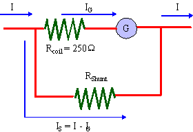
Since the voltage drop across each arm is the same
IGRC = (I − IG)RS .
Solving for RS, we find
RS = IGRC / (I − IG) = (1.5 mA)(250 Ω)/(25 mA − 1.5 mA) = 16 .
We would need the shunt to have a resistance of 16 Ω.
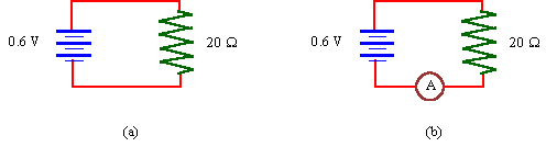
For diagram (a) we just use Ohm's law to determine the current
For diagram (b) we must remember that this ammeter has a resistance RA = 15 W which is not much smaller that the resistance already there 20 Ω. The equivalent resistance of the circuit in (b) is therefore
Now using Ohm's law to determine the current
![[Return to Top of Page]](./../../top.gif)
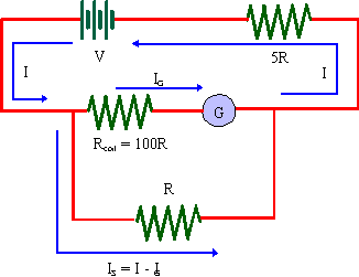
With the ammeter in place, the current produced by the battery is I = V/Req, where
Req = 5R + (1/R + 1/100R)-1 = (605/101)R .
Thus
| I = (101/605)(V/R) | (1) |
When the ammeter is not in the circuit the current will be
| I0 = V/5R | (2) |
We can use equation (1) to eliminate V/R from equation (2),
| I0 = (1/5)(605/101)I = (121/105)I | (3) |
So to find I0 we need to know I. Looking at the parallel arms of the ammeter we see that the voltage drop must be the same over each arm
IG(100R) = (I - IG)R .
Solving for I yields I = 101IG. Using this result with (3) gives
I0 = (121/105)I = (121/105)(101)(10 × 10-3 A) = 1.22 A .
A voltmeter is connected is parallel with the resistor of interest, as shown in the diagram below
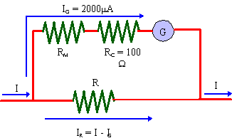
Since the voltmeter is parallel with the resistor, the voltage drop across both is the same. The voltage drop across the coil is
Vcoil = (RM + RC)IG .
Solving for RM, yields
RM = V/IG - RG = (1.5 V / 2000 A) - 100 Ω = 650 Ω .
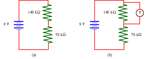
For diagram (a) we can determine the potential difference over the 140 kΩ resistor quite simply. It is twice as big as the 70 kW resistor. Hence it uses twice as much energy and so has twice the potential difference. That is it gets 2/3 × 9 Volts = 6 Volts.
For diagram (b) we must remember that this voltmeter has a resistance RV = 140 k&Omeg a which is not much greater that the resistance it is connected in parallel with, 140 k Ω. The equivalent resistance of the voltmeter and the 140 kΩ resistor in (b) is therefore
This equivalent resistance is the same size as the other resistor in circuit so each shares the half the potential difference or ½ × 9 Volts = 4.5 Volts. Now recall that the equivalent resistance and the two parallel resistors must each have the same potential difference. So the 140 kΩ resistor has 4.5 Volts over it and that is what the voltmeter displays.
The time constant is given by τ
= RC,
hence
R = τ/C = 3.0 s / 750 μF = 4.0 kΩ .
The behaviour of discharging capacitors is given by
Q(t) = Q0e-t/RC .
We are given that Q(t = 8.3 s) = 0.01Q0. So we have
0.01Q0 = Q0e-t/RC.
Eliminating Q0, and taking the natural logarithm of both sides yields
ln(0.01) = -t/RC .
Hence
C = -t / Rln(0.01) = -(8.3 s)/(9600 Ω)ln(0.01) = 188 μF .
The behaviour of discharging capacitors is given by
Q(t) = Q0e-t/RC .
We are asked to find t such that Q(t) = ½Q0. So we have
½Q0 = Q0e-t/RC .
Eliminating Q0, and taking the natural logarithm of both sides yields
ln(0.5) = -t/RC .
Hence
t = -RC ln(0.5) = -(5.8 × 10⁸Ω)(8.0 × 10⁻⁶μF)ln(0.5) = 2.77 × 10³ s = 46.2 min .
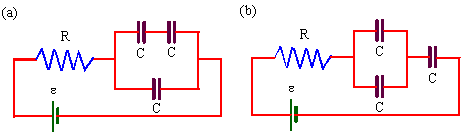
The equivalent capacitance in circuit (a) is Ca = 3C/2. Thus the time constant is τa = 3RC/2 . The equivalent capacitance in circuit (b) is Cb = 2C/3. Thus the time constant is τb = 2RC/3 . Hence
τb = (2/3)(2/3)(3RC/2) = (4/9)τa = (4/9)(0.020 s) = 0.0089 s .
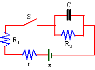
There are two approaches that can be taken. We can apply Kirchhoff’s Rules to the circuit some time after switch S is closed while the capacitor is still charging and there are currents in all branches. We derive a set of equations and we then use our knowledge of the t = 0 and t = ∞ behaviour of capacitors to simplify and solve. This is guaranteed to work in all cases. We will do this first.
First we identify nodes and assign currents to each branch as shown in the next diagram.
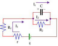
| ε − rI1 − R1I1 − Vc = 0 | [1] |
| Vc − R2I2 = 0 | [2] |
| I1 = Ic + I2 | [3] |
(a) At t = 0, the capacitor is uncharged and Vc = q/C = 0. As a result, equation [2] indicates that I2 = 0 which means resistor R2 has been shorted. Equation [1] simplifies and we find the current from the battery to be I1 = ε/(r + R1) = 10/5.5 A = 2.18182 A.
(b) At t = ∞, the capacitor is fully charged and there is no current in that branch, Ic = 0. As a result, equation [3] indicates that I2 = I1. This is equivalent to the capacitor acting as an open and all the current entering the node passing through resistor R2. Equation [2] then yields Vc = R2 I1. Substituting this last result into equation [1], we have ε − rI1 − R1I1 − R2I1 = 0. Solving for the battery current, I1 = ε/(r + R1 + R2) = 12/15.5 A = 0.77419 A.
(c) Since, we have current I1 we can find the voltage over the capacitor Vc = R2I1 = 7.7419 V. With the voltage known, QQ = CV = 1935.5 μC.
(d) When switch S is opened, I1 = 0. Equation [1] above no longer applies because the loop is not closed. Equation [2] does apply and the initial discharge current of the capacitor is I2 = Vc/R2 = 7.7419/10 A = 0.77419 A.
The behaviour of discharging capacitors is given by
Q(t) = Q0e-t/RC.
We are asked to find t such that Q(t) = 0.2Q0. So we have
0.2Q0 = Q0e-t/RC.
Eliminating Q0 and taking the natural logarithm of both sides yields
ln(0.2) = -t/RC .
Hence
t = -RC ln(0.2) = -(10.0 Ω) (250 μF) ln(0.2) = 4.02 × 10⁻³ s .
An alternate approach is to use our knowledge of the t=0 and t = ∞ behaviour of capacitors and reduce the circuit to combinations of series and parallel resistors. This may not always be possible as there are combinations of resistors that are neither series nor parallel.
(a) Initially, the capacitor acts like a short circuit bypassing R2. The circuit's behaviour is identical to
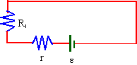
Thus the current through the series combination is
I = ε/(r + R1) = (12.0 V) / (5.5 Ω) = 2.18 A .
(b) After a long time the capacitors acts as an open switch and all the resistors are in series. The circuit is now identical to
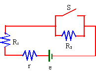
Thus the current through the series combination is
I = ε/(r + R1 + R2) = (12.0 V)/(15.5 Ω) = 0.774 A .
(c) The capacitor is in parallel with R2, so the must both have the same voltage drop. From Ohm's Law, we find the voltage drop to be
VC = V2 = IR2 = (0.774 A)(10.0 Ω) = 7.74 V .
The charge on the capacitor is then given by
Q = CVc = (250 μF)(7.74 V) = 1.94 mC .
(d) The behaviour of discharging capacitors is given by
Q(t) = Q0e-t/RC .
We are asked to find t such that Q(t) = 0.2Q0. So we have
0.2Q0 = Q0e-t/RC .
Eliminating Q0, and taking the natural logarithm of both sides yields
ln(0.2) = -t/RC .
Hence
t = -RC ln(0.2) = -(10.0 Ω) (250 μF) ln(0.2) = 4.02 × 10⁻³ s .
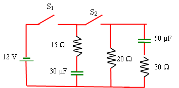
Consider the circuit below. Both capacitors are
initially uncharged. Switch S2 is closed followed by S1.
(a) At that instant what is the conventional current (magnitude and direction)
in each resistor?
(b) After the switches have been closed for a long time, what is the
conventional current (magnitude and direction) in each resistor?
(c) Now S2 (and only S2) is reopened. At this instant
what is the conventional current (magnitude and direction) in each resistor?
(d) How long will it take for the current in the 30Ω resistor to
drop to 0.10 A?
There are two approaches that can be taken. We can apply Kirchhoff’s Rules to the circuit some time after the switches are closed and the capacitors are charging and there are currents. We derive a set of equations and we then use our knowledge of the t = 0 and t = ∞ behaviour of capacitors to simplify and solve. This is guaranteed to work in all cases. We will do this first.
First we identify nodes and assign currents to each branch as shown in the next diagram. Note that nodes connected by resistanceless wires are the same node. This is indicated by the purple bars in the diagram below. There are only two nodes in this circuit. Second, the polarity of capacitors is dictated by the assumed direction of the currents. The conventional current is depositing positive charge to the plate it encounters first.
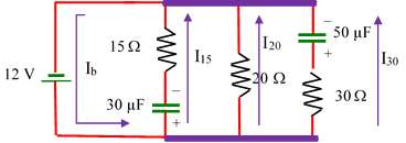
Since one branch has a single battery, I will include that in every loop equation. The equations will be simpler as a result.
| 12 − V30 − 15I15 = 0 | [1] |
| 12 − 20I20 = 0 | [2] |
| 12 − 30I30 − V50 = 0 | [3] |
| Ib = I15 + I20 + I30 | [4] |
(a) At t = 0, the is no charge on the capacitors and no voltage across the capacitors, i.e. V30 = V50 = 0. The capacitors are acting as bare wire. Each resistor is in parallel with the battery. We find I15 = 12/15 A = 4/5 A. I20 = 12/20 A = 3/5 A, and I30 = 12/30 A = 2/5 A.
(b) At t = ∞, the capacitors are fully charged and they prevent current from flowing in their branches so I15 = I30 = 0. Equation [2] yields I20 = 12/20 A = 3/5 A. From equations [1] and [3] we find V30 = V50 = 12 V.
(c) When S2 is opened, we now have two separate circuits as no current can pass from one side to the other since there is no return path for the current.
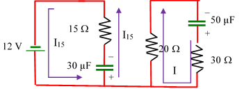
On the battery circuit, the capacitor is still fully charged, so I15. On the 50 μF side, the capacitor is fully charged and will discharge through both the 20 Ω and 50 &Omega resistors which are in series. The capacitor was at 12 V, so the current is I = (12 V)/(20Ω + 30 Ω) = 0.24 A.
(d) We know I = I0e-t/RC, for a discharging capacitor, where R is the equivalent resistance of the circuit which is 50 Ω and I0 = 0.24 A from the previous question. Inverting the equation to find t yields,
t = RC ln(I0/I) = 50 Ω × 50μF × ln(0.24/0.10) = 2.2 × 10⁻³ seconds.
An alternate approach is to use our knowledge of the t = 0 and t = ∞ behaviour of capacitors and reduce the circuit to combinations of series and parallel resistors. This may not always be possible as there are combinations of resistors that are neither series nor parallel.
I15 = 12 V / 15 Ω = 0.8 A, I20 = 12 V / 20 Ω = 0.6 A, and I30 = 12 V / 30 Ω = 0.4 A
(b) At t = , the capacitors act as opens and no current will flow through the branches containing them, that is I15 = I30 = 0 A. The 20 Ω resistor will still be in parallel with the battery and will still carry I20 = 12 V / 20 Ω = 0.6 A upwards for conventional current.
(c) When S2 is reopened, the 50 μF capacitor will discharge through the 20 Ω and 30 Ω resistors which are in series. To determine the current, note that in the previous question that the capacitor was fully charged and that it and the 30 Ω resistor were in parallel with the 12 V battery. Since there was no current through the resistor, the capacitor was charged to 12 V. That means now the 12 V across the capacitor will discharge through the two resistors that are in series and act as a single 50 Ω resistor.
The conventional current will clockwise through the loop.
(d) We know I = I0e-t/RC, for a discharging capacitor, where R is the equivalent resistance of the circuit which is 50 Ω and I0 = 0.24 A from the previous question. Inverting the equation to find t yields,
t = RC ln(I0/I) = 50 Ω × 50 μF × ln(0.24 / 0.10) = 2.2 × 10⁻³ seconds.
(a) When the switch is closed in the circuit below what is
the initial current in each resistor?
(b) After the switch has been closed for a long time what is the current
through each resistor?
(c) What is the voltage across the capacitor and its charge at that later time?
(d) If the switch S is reopened, what is the current through each resistor?
(e) How long will it take for the capacitor to lose 70% of its charge (Hint:
what is the equivalent resistance of circuit)?
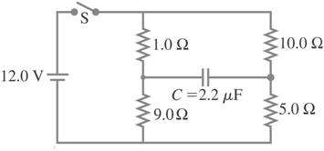
There are two approaches that can be taken. We can apply Kirchhoff’s Rules to the circuit some time after switch S is closed and the capacitor is charging and there are currents. We derive a set of equations and we then use our knowledge of the t = 0 and t = ∞ behaviour of capacitors to simplify and solve. This is guaranteed to work in all cases. We will do this first.
First we identify nodes and assign currents to each branch as shown in the next diagram. There are only three nodes in this circuit. Second, the polarity of the capacitor is dictated by the assumed direction of the current. The conventional current is depositing positive charge to the plate it encounters first. We have three loops when S is closed.
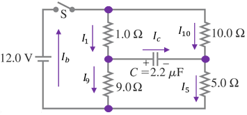
| 12 − 1I1 − 9I9 = 0 | [1] | |
| 12 − 10I10 − 5I5 = 0 | [1a] | unnecessary but helps with later calculations |
| Vc + 1I1 − 10I10 = 0 | [2] | |
| Vc − 9I9 + 5I5 = 0 | [3] | |
| Ib = I1 + I10 | [4] | |
| I1 = Ic + I9 | [5] | |
| Ic + I10 = I5 | [6] | |
| I9 + I5 = Ib | [7] | unnecessary but helps with later calculations |
(a) At t = 0, there is no charge on the capacitor and no voltage across it, Vc = 0. The capacitor acts as a bare wire. Equations [2] and [3] simplify to I10 = (1/10)I1 and I5 = (9/5)I9. The capacitor is acting like a bare wire. The two middle nodes are the same node. The effect is as if these pairs of resistors were in parallel. These results can be inserted into the node equations [4] and [7] yielding Ib = (11/10)I1 and Ib = (14/5)I9 which together yield I9 = (11/28)I1. Substituting this result in loop equation [1] yields, I1 = (28/127)(12) = 2.64567 A. We also find I10 = 0.26457 A, I9 = 1.03937 A, and I5 = 1.87087 A.
(b) At t = ∞, the capacitor is fully charged and it prevents current from flowing in its branch so Ic = 0. Node equations [5] and [6] thus yield I1 = I9 and I10 = I5. The capacitor is acting like an open, the 1Ω and 9Ω resistors are now in series and the 10Ω and 5Ω resistors are in series as well. Equations [1] and [1a] yields I1 = I9 = 12/10 A = 6/5 A and I10 = I5 = 12/15 A = 4/5 A.
(c) Since we have all the currents, we can use equation [2] or [3] to find Vc. From [2] we have Vc = 10 I10 − 1I1 = 40/5 − 6/5 = 34/5 V = 6.8 V. The charge on the capacitor is Q = CV = (2.2 μF)(6.8 V) = 14.96 μC.
(d) When switch S is reopened, Ib = 0 since there is no circuit including the battery and equation [1] and [1a] no longer apply. The circuit will look like
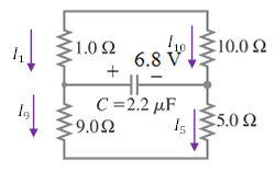
Since Ib = 0, equations [4] and [7] reduce to I10 = −I1 and I9 = −I5. We have Vc and can use equation [2] or [3] to work out the currents. Using [2] yields Vc = −11I1 or I1 = −Vc/11 = −6.8/11 A = −0.61818 A. Thus I10 = +0.61818 A. Using [3] yields Vc = −14I5 or I5 = −Vc/14 = −6.8/14 A = −0.48571 A. Thus I9 = +0.48571 A. Note that currents I1 and I5 are now running in the opposite direction to that shown in the diagram above. Since the current in the 1 Ω resistor and the 10 Ω resistor is the same, these two resistors are in series. Similarly the 9 Ω and 5 Ω resistors are also in series.
(e) We only know the equation for a single capacitor discharging through a single resistor. We first need the equivalent resistance of the circuit. We can do this by noting the 1 Ω resistor and the 10 Ω resistor are in series and that the 9 Ω and 5 Ω resistors are also in series. Since this '11 Ω' resistor and the '14 Ω' resistor share two nodes, they are in parallel and can be reduced to a single resistor.
R = (1 / 11 Ω + 1 / 14 Ω)-1 = 6.16 Ω.
We know I = I0e-t/RC for a discharging capacitor, where R is the equivalent resistance of the circuit which is 6.16 Ω. Inverting the equation to find t yields,
t = RC ln(I0/I) = 6.16 Ω × 2.2 μF × ln(1 / 0.70) = 4.83 × 10⁻⁶ seconds.
An alternate approach is to use our knowledge of the t = 0 and t = ∞ behaviour of capacitors and reduce the circuit to combinations of series and parallel resistors. This may not always be possible as there are combinations of resistors that are neither series nor parallel.
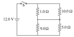
(a) At t = 0, capacitors act as shorts (a straight wire with no resistance). Thus the 1.0 Ω and 10.0 Ω resistors are in parallel and similarly the 9.0 Ω and 5.0 Ω are in parallel. These pairs can be replaced by their equivalent resistors, 0.90909 Ω and 3.21429 Ω respectively, as shown below.
 |
⇒ | 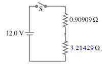 |
Using the voltage divider formula, the voltage across the 3.21429 Ω resistor is
12.0 V × 3.21429 Ω / (0.90909 Ω + 3.21429 Ω) = 9.35434 Volts.
This is also the voltage across both the 5.0 Ω and 9.0 Ω resistors, so using Ohm’s Law
I9 = 9.35434 V / 9 Ω = 1.03937 A and I5 = 9.35434 V / 5 Ω = 1.87087 A
The voltage drop across the 0.90909 Ω resistor is 12.0 V – 9.35434 V = 2.64566 V. This is also the voltage across the 1.0 Ω and 10.0 Ω resistors. Again using Ohm’s Law,
I1 = 2.64566 V / 1 Ω = 2.64566 A and I10 = 2.64566 V / 10 Ω = 0.26457 A.
(b) At t = ∞, the
capacitor acts as an open and no
current will flow through that branch. The 1.0 Ω
and 9.0 Ω resistor are now in series in
one branch with the 10.0 Ω and
5.0 Ω in series in the other as shown below.
12.0 V × 9.0 Ω / (1.0 Ω + 9.0 Ω) = 10.8 V.
Which means the voltage drop over the 1.0 Ω resistor is 12.0 V – 10.8 V = 1.2 V.
Similarly the voltage drop over the 5.0 Ω resistor is
12.0 V × 5.0 Ω / (10.0 Ω + 5.0 Ω) = 4.0 V
and the remaining voltage drop over the 10.0 Ω resistor is 12.0 V – 4.0 V = 8.0 V.
Using Ohm’s Law the current through each resistor is
I1 = 1.2 V / 1 Ω = 1.2 A, I9 = 10.8 V / 9 Ω = 1.2 A,
I10 = 8.0 V / 10 Ω = 0.8 A, and I5 = 4.0 V / 5 Ω = 0.8 A.
(c) To find the voltage drop across the capacitor, we apply Kirchhoff’s voltage rule to any loop that contains the capacitor. Going clockwise from the capacitor
VC + (1.0 Ω) I1 – (10.0 Ω)I10 = 0.
Using the currents from the previous question, VC = 8 V – 1.2 V = 6.8 V.
(d) When switch S is reopened the active circuit is
Kirchhoff's voltage rule for the top loop is 6.8 V – Itop(1.0 Ω + 10.0 Ω) = 0, which means the current through these resistors is 0.61818 A. Similarly, Kirchhoff’s voltage rule for the bottom loop is 6.8 V – Ibottom(9.0 Ω + 5.0 Ω) = 0, which means the current through these resistors is 0.48571 A.
(e) First, as suggested, let’s find the equivalent resistance. The top branch has a series equivalent resistance of 11.0 Ω while the bottom branch has a series equivalent resistance of 14.0 Ω. The top and bottom branch are in parallel, so they may be replaced by a single equivalent resistor
R = (1 / 11 Ω + 1/ 14 Ω)-1 = 6.16 Ω.
We know I = I0e-t/RC for a discharging capacitor, where R is the equivalent resistance of the circuit which is 6.16 Ω. Inverting the equation to find t yields,
t = RC ln(I0/I) = 6.16 Ω × 2.2 μF × ln(1 / 0.70) = 4.83 × 10⁻⁶ seconds.
Consider
the RC circuits shown below. The voltage drop and its direction
for the capacitor are given. Find the current and its direction at the
instant
the switch S is closed.
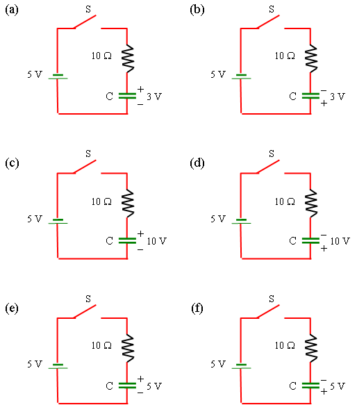
We apply Kirchhoff’s voltage rule to each circuit being careful to note the polarity of the battery and the capacitor. Let’s assume the current is counterclockwise in each circuit and go around the loop in the same direction.
(a) 5 V + 3 V – I(10) = 0. Thus I = 0.8 A counterclockwise.
(b) 5 V – 3 V – I(10) = 0. Thus I = 0.2 A counterclockwise.
(c) 5 V + 10 V – I(10) = 0. Thus I = 1.5 A counterclockwise.
(d) 5 V – 10 V – I(10) = 0. Thus I = –0.5 A (– means clockwise).
(e) 5 V + 5 V – I(10) = 0. Thus I = 1.0 A counterclockwise.
(f) 5 V – 5 V – I(10) = 0. Thus I = 0 A.
Questions?mike.coombes@kpu.ca
![[Return to Kwantlen Homepage]](http://www.kpu.ca/images/return_button.gif)