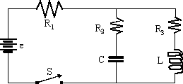
In the circuit diagram shown below, the capacitor is initially
uncharged.
(a) When switch S is initially closed, what are the currents
through each resistor?
(b) When switch S has been closed for a very long time, what are
the currents through each resistor?
(c) Assuming that the charge on the capacitor has the form, q(t)
= Q0 + Q1e-kt, and that the currents
obey
i(t) = I0 + I1e-kt, find
expressions for the time dependence of the charge and currents.
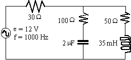
For the circuit shown below, use the phasor method to determine
the impedance of the circuit and the current (including phase)
through 30 Ω resistor. Does the current
lead or lag the voltage?
In class, we looked at the series RC circuit. By looking at
the ratio of the RMS values of the output (i.e. resistor) voltage
to the input (i.e. power supply) voltage, we saw how that it was
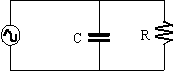
a high-pass frequency filter. The diagram below shows a parallel
RC circuit. Looking at voltages for this circuit is not useful,
of course, so we consider currents.
(a) Find an expression for the ratio of the RMS values of
the output current to the input current.
(b) For R = 105 Ω and C
= 0.16 μF,
plot the ratio on a log-log graph. Consider frequencies from 0.1 Hz to 106
Hz. Is the circuit a filter? Which kind, high-pass or low-pass?
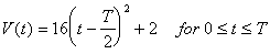
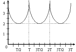
The signal in the diagram below is given by the equation
Find
(a) the average voltage,
(b) the rms voltage,
(c) the AC-RMS voltage, and
(d) the DC equivalent voltage which would produce the same
power dissipation in a resistor.
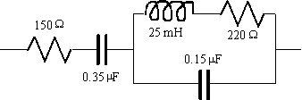
Determine the complex impedance of the circuit shown below
at f = 1250 Hz. Is the circuit inductive or capacitive (explain why)?
A sinusoidal 10.0 Volt signal at 800 Hz is fed into a transformer
with Nin:Nout = 1:5. The signal from the
transformer is then passed through a bridge rectifier using Germanium
diodes (VB = 0.3 V). This signal is then passed through
either a capacitor filter (C = 40.0 μF)
or an L-section filter (C = 40.0 μF and
L = 50.0 mH and Rinductor = 15 Ω)
to a load resistance of 500 Ω.
(a) What is the ripple factor in each case?
(b) What is the peak output voltage for each?
(c) What is the DC output voltage for each?
![[Return to Physics Homepage]](../physics.gif)
![[Return to Mike Coombes' Homepage]](../coombes.gif)
![[Return to List of Handouts]](../handouts.gif)
![[Return to Sample Tests]](../tests.gif)
![[Return to Kwantlen Homepage]](http://www.kpu.ca/images/return_button.gif)