![[Return to Physics Homepage]](./../../physics.gif)
![[Return to Mike Coombes' Homepage]](./../../coombes.gif)
![[Return to List of Handouts]](./../../handouts.gif)
![[Return to Problem Sets]](./../../problems.gif)
![[Return to List of Solutions]](./../../solutions.gif)
| Questions: 1 | 2 | 3 | 4 | 5 | 6 | 7 | 8 | 9 | 10 | 11 | 12 | 13 | 14 | 15 | 16 |

The problem expects you to recall that the mass of an oxygen atom is 16 times that of a hydrogen atom. The first step is to choose a coordinate system, such as the one in the diagram, and locate each particle. The chosen origin is the centre of the box.

| Atom | Mass (H) | xi | yi | mixi | miyi |
| H | 1 | -0.0958sin15 | 0.0958cos15 | -0.02479 | 0.09254 |
| O | 16 | 0 | 0 | 0 | 0 |
| H | 1 | 0.0958 | 0 | 0.0958 | 0 |
| Totals: | 18 | 0.07101 | 0.09254 |
The coordinates of the centre of mass are given by
The centre of mass is located at (0.0039 nm, 0.0051 nm). Answers will vary based on the choice of coordinate system.
![[Return to Top of Page]](./../../top.gif)
In dealing with real objects rather than particles, we treat the complex object as a grouping of simpler shapes. The CM of the simpler shapes is at their easy to find geometric centre if the object is uniform. Each pierce can now be considered a particle with the mass of the piece located at the CM of that piece. We have, in effect, turned the complex shape into a collection of particles. In this case, each of the five sides can be considered a separate particle.
The next step is to choose a coordinate system, such as the one in the diagram below, and locate each particle. The origin is at the centre of the box.
| Side | Mass | xi | yi | zi | mixi | miyi | mizi |
| bottom | M | 0 | 0 | -½L | 0 | 0 | -½ML |
| front | M | 0 | -½L | 0 | 0 | -½ML | 0 |
| back | M | 0 | ½L | 0 | 0 | ½ML | 0 |
| left | M | -½L | 0 | 0 | -½ML | 0 | 0 |
| right | M | ½L | 0 | 0 | ½ML | 0 | 0 |
| Totals: | 5M | 0 | 0 | -½ML |
The coordinates of the centre of mass are given by
The centre of mass is located at (0, 0, -L/10). Answers will vary based on the choice of coordinate system.
It is also permissible to use symmetry arguments. For example,
the figure in the diagram is only unbalanced in the z direction,
thus we know that xcm = ycm = 0. We only
needed the z columns in the above table.
In dealing with real objects rather than particles, we treat the complex object as a grouping of simpler shapes. The CM of the simpler shapes is at their easy to find geometric centre if the object is uniform. Each pierce can now be considered a particle with the mass of the piece located at the CM of that piece. We have, in effect, turned the complex shape into a collection of particles. In this case, we have one particle of mass M located in the centre of the lighter side, and a mass of 2M in the centre of the heavier side.
The next step is to choose a coordinate system, such as the one in the diagram below, and locate each particle. The origin is in the centre of the join of the two plates.
Using the symmetry of the problem, we see that the CM must be located in the xz plane, we know that ycm = 0.
| Side | Mass | xi | zi | mixi | mizi |
| side | M | 0 | ½L | 0 | ½ML |
| bottom | 2M | ½L | 0 | ML | 0 |
| Totals: | 3M | ML | ½ML |
The components of the centre of mass are given by
The centre of mass is located at (L/3, 0, L/6). Answers will vary based on the choice of coordinate system.
In dealing with real objects rather than particles,
we treat the complex object as a grouping of simpler shapes.
The CM of the simpler shapes is at their easy to find geometric
centre if the object is uniform. Each pierce can now be considered
a particle with the mass of the piece located at the CM of that
piece. We have, in effect, turned the complex shape into a collection
of particles. In this case, we have a solid cube and a cylindrical
hole. We treat holes as objects of negative mass.
To proceed we need to know the mass of the cylindrical hole. Since the object was uniform, its mass is proportional to its volume. The solid cube had a mass M and a volume L3. The cylinder has a volume Vcyl = r2L = L3/16. Thus the mass of the cylindrical hole is
The next step is to choose a coordinate system, such as the one in the diagram below, and locate each particle.

Using the symmetry of the problem, we see that the CM must be located in the x axis, we know that ycm = zcm = 0.
| Side | Mass | xi | mixi |
| solid cube | M | 0 | 0 |
| hole | -πM/16 | -¼L | πML/64 |
| Totals: | M(1-π/16) | πML/64 |
The location of the x component of the centre of mass is given by
The centre of mass is located at (πL / 64(1-π/16), 0, 0). Answers will vary based on the choice of coordinate system.
The logger and the log are a system; the system has a certain centre of mass. The motion of the logger is an internal force; internal forces cannot change the centre of mass of the system.

Examining the diagram, the log has moved down the river a distance equal to twice the distance between the centre of the log and the CM of the logger-log system. We need to find the CM of the logger-log system. Taking the origin as the end of the log,
Since the centre of the log is at 5 m, distance between the CM and the centre of the log is 1.05 m. The log moved twice this distance or 2.11 m.
The pieces of the shell are a system; the system has a certain centre of mass. The explosion is an internal force; internal forces cannot change the centre of mass of the system. The CM of the pieces will land where the CM of an unexploded shell will land.

The first step is to find xcm, the landing position of the shell. That involves solving the projectile motion problem.
| i | j |
| x = xcm = ? | y = 0 |
| ax = 0 | ay = -g = -9.81 m/s |
| v0x = 25cos25 = 22.658 m/s | v0y = 25sin25 = 10.565 m/s |
| t = ? | t = ? |
The j information allows us to find the time in
air using y = v0yt - ½gt2. Since y
= 0, this reduces to
We then find the landing position using x = v0xt + ½axt2. Since ax = 0,
The centre of mass is determined by the formula
Since we now know xcm and x2, we can rearrange to find m1,
So the smaller piece lands 26.4 m from where the shell was fired.

There are two methods for determining torque. Method A is to use τz = rFsinθ, where r is the distance from the pivot point to the point where the force F acts and θ is the angle between r and F. The sign of τz is found using the right-hand rule. Method B is to use τz = xFy - yFx, where (x, y) is the location of where the force is acting taken relative to the pivot point which is taken to be the origin (0, 0). Fx and Fy are the components of the force - careful attention must be paid to signs.
Method A.
First note that the interior angles of the triangle are α
= tan-1(4/3) = 53.130°, and γ
= tan-1 (3/4) = 36.870°. F2 makes an angle
φ = 180° - 110°
- γ = 16.870° with the vertical.
(a)

| r (m) | F (N) | θ | direction | τz = rFsinθ (N-m) |
| 0 | 91.7 | - | - | 0 |
| 5 | 150 | 110° | CCW | 704.769 |
| 2 | 67.7 | 130° | CW | -103.722 |
| Total: | 601.0 |
(b)

| r (m) | F (N) | θ | direction | τz = rFsinθ (N-m) |
| 4 | 91.7 | 90° | CCW | 366.800 |
| 3 | 150 | 110° + γ | CCW | 130.591 |
| 2 | 67.7 | 50° | CCW | 103.722 |
| Total: | 601.1 |
(c)

| r (m) | F (N) | direction | τz = rFsinθ (N-m) | |
| 5 | 91.7 | 90° + α | CCW | 366.800 |
| 0 | 150 | - | - | 0 |
| 3.60555 | 67.7 | 50° + 56.130° | CCW | 234.272 |
| Total: | 601.1 |
Method B:
(a)

| x (m) | y (m) | Fx (N) | Fy (N) | τz = xFy - yFx (N-m) |
| 0 | 0 | 0 | -91.7 | 0 |
| 4 | 3 | -150sinφ | 150cosφ | 704.769 |
| 2 | 0 | 67.7cos50° | -67.7sin50° | -103.722 |
| total: | 601.0 |
(b)

| x (m) | y (m) | Fx (N) | Fy (N) | τz = xFy - yFx (N-m) |
| -4 | 0 | 0 | -91.7 | 103.722 |
| 0 | 3 | -150sinφ | 150cosφ | 130.591 |
| -2 | 0 | 67.7cos50° | -67.7sin50° | 366.80 |
| total: | 601.1 |
(c)

| x (m) | y (m) | Fx (N) | Fy (N) | τz = xFy - yFx (N-m) |
| -4 | -3 | 0 | -91.7 | 366.800 |
| 0 | 0 | -150sinφ | 150cosφ | 0 |
| -2 | -3 | 67.7cos50° | -67.7sin50° | 234.272 |
| total: | 601.1 |
Please note that the only reason the total torque at point A, B, and C are the same is because F1 + F2 + F3 = 0.
The problem mentioned that the object is free to pivot, to rotate. This indicates that we are dealing with a Static Equilibrium problem. We solve Static Equilibrium problems by sketching the extended free-body diagram, an FBD where the location of the all forces are indicated so that torques can be calculated. Then we determine the three equations necessary for static equilibrium, ΣFx = 0, ΣFy = 0, and Στz = 0.
The forces that we know are working on the L-shaped object are a normal from the nail and the weight which acts from the centre of mass. Ordinarily, for complex shapes, we first determine the CM. However, in this case, it is easier to consider the two arms of the objects as being separate objects. The long arm will have a mass (2/3)mg and the short arm will be (1/3)mg. We do not have a simple method of figuring out which way the normal points. As with all pins, we consider it as two forces one vertical and one horizontal.
| ΣFx = 0 | ΣFy = 0 |
| Nx = 0 | Ny - (1/3)mg - (2/3)mg = 0 |
These tell us the obvious, the normal has no horizontal component
and that it supports the weight of the object.
We will use Method A for the torques since that method is easiest to apply here. We will take the nail as the pivot point since this eliminates the torques from the nail.
| r | F | direction | τz = rFsinθ | |
| 0 | Nx | - | - | 0 |
| 0 | Ny | - | - | 0 |
| L/2 | (1/3)mg | ½π-θ | CW | -mgLsin(½π-θ)/6 |
| L | (2/3)mg | θ | CCW | 2mgLsinθ/3 |
Since Στz = 0, the equation we get is
Eliminating common terms and noting sin(½π-θ) = cosθ, this becomes
or
Using the identity,
tanθ = sinθ/cosθ,
we thus have θ = tan-1(1/4) = 14.0°.
The long side makes a 14.0° angle with the vertical.

The problem mentions forces and looking at the diagram shows
that the object would rotate in the absence of any one of these
forces. This indicates that we are dealing with a Static Equilibrium
problem. We solve Static Equilibrium problems by sketching the
extended free-body diagram, an FBD where the location of the all
forces are indicated so that torques can be calculated. Then
we determine the three equations necessary for static equilibrium,
ΣFx = 0,
ΣFy = 0,
and Στz = 0.
The forces that we know are working on the boom are a normal from the pin, the weight which acts from the centre of mass, and the two tensions. We are given T2. The CM is obviously at the centre of the boom. We do not have a simple method of figuring out which way the normal points, instead we consider it as two forces one vertical and one horizontal.

| ΣFx = 0 | ΣFy = 0 |
| Px - T1 = 0 | Py - mg - T2 = 0 |
These tell us the obvious, that Px = T1
and Py = mg + T2 = 2400 N.
We will use Method A for the torques since that method is easiest to apply here since the distances and angles are relatively easy to find. We will take the pin as the pivot point since this eliminates the torques from the pin.
| r | F | θ | direction | τz = rFsinθ |
| 0 | Px | - | - | 0 |
| 0 | Py | - | - | 0 |
| L/2 | W | 40° | CW | -LWsin(40°)/2 |
| (3/4)L | T1 | 50° | CCW | 3LT1sin(50°)/4 |
| L | T2 | 40° | CW | -LT2sin(40°) |
Since Στz = 0, the equation we get is
Eliminating L from the above and rearranging to get T1
by itself yields,
Using the values we are given, we find T1 = 2461 N.
Since we know Px = T1, we also know the
pin
force is
The magnitude of this force is P = [(Px)2
+ (Py)2 ]½ = 3438 N. The
force is directed at an angle θ = tan-1(Py/Px)
= 44.3° to the horizontal. Note that the pin force is not pointed
solely along the length of the boom as one might expect.
Big Point To Remember: Pin forces are not always directed in the obvious direction.
The problem mentions forces and looking at the diagram
shows that the object would rotate in the absence of any one of
these forces. This indicates that we are dealing with a Static
Equilibrium problem. We solve Static Equilibrium problems by
sketching the extended free-body diagram, an FBD where the location
of the all forces are indicated so that torques can be calculated. Then
we determine the three equations necessary for static equilibrium,
ΣFx = 0,
ΣFy = 0,
and Στz = 0.
The forces that we know are working on the boom are a normal from the pin, the weight which acts from the centre of mass, and the two tensions. The CM is obviously at the centre of the boom. We do not have a simple method of figuring out which way the normal points, instead we consider it as two forces one vertical and one horizontal.

| Fx = 0 | ΣFy = 0 |
| Px - T1cos(π/2-θ) = 0 | Py - mg - T2 - T1sinθ = 0 |
These tell us that Px = T1cosθ and Py = mg + T2 + T1sinθ. We are given the mass of the load so we know T2 = mloadg = 4905 N.
We will use Method A for the torques since that method is easiest to apply here since the distances and angles are relatively easy to find. We will take the pin as the pivot point since this eliminates the torques from the pin.
| r | F | θ | direction | τz = rFsinθ |
| 0 | Px | - | - | 0 |
| 0 | Py | - | - | 0 |
| L/2 | mg | π/2 - φ | CW | -Lmgsin(π/2-φ)/2 |
| L | T1 | θ - φ | CCW | LT1sin(θ-φ) |
| L | T2 | π/2 - φ | CW | -LT2sin(π/2-φ) |
Since Στz = 0, the equation we get is
Eliminating L from the above, multiplying through by 2, and using
the identity that sin(π/2-φ)
= cosφ yields,
We rearrange to get T1 by itself,
Using the values we are given, and the value for T2, we find T1 = 15008 N.
We have Px = T1cosθ =
12998 N. As well,
Py = mg + T2 + T1sinθ
= 13587 N. Thus we also know that the pin force is
The magnitude of this force is P = [(Px)2
+ (Py)2 ]½ = 1.88 × 10⁴
N. The force is directed at an angle θ = tan-1(Py/Px)
= 46.3° to the horizontal. Note that the pin force is not pointed
solely along the length of the boom as one might expect.

The problem mentions forces and looking at the diagram
shows that the object would rotate in the absence of any one of
these forces. This indicates that we are dealing with a Static
Equilibrium problem. We solve Static Equilibrium problems by
sketching the extended free-body diagram, an FBD where the location
of the all forces are indicated so that torques can be calculated. Then
we determine the three equations necessary for static equilibrium,
ΣFx = 0,
ΣFy = 0,
and Στz = 0.
The forces that we know are working on the sign are a normal from the pin, the weight which acts from the centre of mass, and the tension. The CM is obviously at the centre of the sign. We do not have a simple method of figuring out which way the normal points, instead we consider it as two forces one vertical and one horizontal.

| ΣFx = 0 | ΣFy = 0 |
| Px + Tsinθ = 0 | Py - mg + Tcosθ = 0 |
These tell us that Px = -Tsinθ and
Py = mg - Tcosθ.
We will use Method B for the torques since that method is easiest to apply here since the location of the forces easy to find. We will take the pin as the pivot point since this eliminates the torques from the pin.
| x | y | Fx | Fy | τz = xFy - yFx |
| 0 | 0 | Px | Py | 0 |
| w | 0 | Tsinθ | Tcosθ | wTcosθ |
| w/2 | -l/2 | 0 | -mg | -wmg/2 |
Since Στz = 0, the equation we get is
Eliminating w from the above and rearranging yields,
The force equations give Px = -Tsinθ = -526 N and Py = mg - Tcosτq = 245.0 N. The minus sign for Px indicates we were wrong in assuming the the hinge pushed the sign to the right, it actually pulls the sign to the left.
Thus the tension in the rope is 580 N and the horizontal and vertical components of the pin force are 526 N and 245 N respectively.

To find the CM, we consider the squares as each having mass M/3 located at their geometric centres. We will set the origin at the upper right corner where the string is attached. Note the symmetry of the object is such that the CM must be located along a vertical line through the centre, that is the CM must be located in the y axis and that xcm = -0.16 m and zcm = 0.
| Piece | Mass | yi (m) | miyi |
| top | M/3 | -0.16 | -0.053333M |
| left | M/3 | -0.48 | -0.16M |
| right | M/3 | -0.48 | -0.16M |
| Totals: | M | -0.373333M |
Thus ycm = (Σmiyi)/Mtotal
= -0.373333 m.
The problem mentions forces and looking at the diagram shows
that
the object would rotate in the absence of any one of these forces. This
indicates that we are dealing with a Static Equilibrium
problem. We solve Static Equilibrium problems by sketching the
extended free-body diagram, an FBD where the location of the all
forces are indicated so that torques can be calculated. Then
we determine the three equations necessary for static equilibrium,
ΣFx = 0,
ΣFy = 0,
and Στz = 0.
The forces that we know are working on the sign are the two tensions and the weight which acts from the centre of mass.
| ΣFx = 0 | ΣFy = 0 |
| T1sinθ - T2sin(65°) = 0 | T1cosτq + T2cos(65°) - Mg = 0 |
These tell us that T1sinθ
= T2sin(65) and
T1cosθ + T2cos(65°) = Mg.
We will use Method B for the torques since that method is easiest to apply here since the location of the forces easy to find. We will locate the pivot at the upper right corner because we have two unknowns there.
| x(m) | y( m) | Fx | Fy | τz = xFy - yFx |
| 0 | 0 | T1sinθ | T1cosθ | 0 |
| -0.64 | -0.32 | -T2sin(65°) | T2cos(65°) | 0.64T2(65°) - 0.32T2sin(65°) |
| -0.16 | -0.37333 | 0 | -Mg | 0.16Mg |
Since Στz = 0, the equation we get is
Rearranging the above yields the tension in the left string,
The force equations give
Taking the ratio of these two results we have
sinθ/cosθ = 0.31725/1.07831
or tanθ = 0.2942. So the unknown angle is
θ = 16.4°. Substituting
the angle back into either of the two equations yields the tension
in the right string T1 = 1.124 N.

To find the CM, we break the sign into two pieces
each having all its mass located at their geometric centres.
Since the sign is uniform, its mass is proportional to its area.
The total area of the sign is 9l2. The crosspiece
has an area of 5l2 while the area of the vertical
piece is 4l2. If the sign has mass M, the crosspiece
therefore has a mass of (5/9)M and the vertical piece a mass of
(4/9)M. We will set the origin at the hinge Note the symmetry
of the object is such that the CM must be located along a vertical
line through the centre, that is the CM must be located in the
y axis and that xcm = 2.5l and
zcm = 0.
| Piece | Mass | yi (m) | miyi |
| top | (5/9)M | ½l | (5/18)Ml |
| bottom | (4/9)M | -2l | -(8/9)Ml |
| Totals: | M | -(11/18)Ml |
Thus ycm = (Σmiyi)/Mtotal
= -(11/18)l.
The problem mentions forces and looking at the diagram shows
that
the object would rotate in the absence of any one of these forces.
This indicates that we are dealing with a Static Equilibrium
problem. We solve Static Equilibrium problems by sketching the
extended free-body diagram, an FBD where the location of the all
forces are indicated so that torques can be calculated. Then
we determine the three equations necessary for static equilibrium,
ΣFx = 0,
ΣFy = 0,
and Στz = 0.
The forces that we know are working on the sign are the tension,
and the weight which acts from the centre of mass, and the normal
force from the hinge. Since we do not know the direction of the
normal force, we show components.
| ΣFx = 0 | ΣFy = 0 |
| -Hx + Tsin(40°) = 0 | Hy + Tcos(40°) - Mg = 0 |
These tell us that Hx = Tsin(40°) and Hy
+ Tcos(40°) = Mg.
We will use Method B for the torques since that method is easiest to apply here since the location of the forces easy to find. We will locate the pivot at the hinge because we have two unknowns there.
| x | y | Fx | Fy | τz = xFy - yFx |
| 0 | 0 | Hx | Hy | 0 |
| 5l | l | Tsin(40°) | Tcos(40°) | 5lTcos(40°) - lTsin(40°) |
| (5/2)l | (-11/18)l | 0 | -Mg | -(5/2)lMg |
Since Στz = 0, the equation we get is
Eliminating l and rearranging the above yields the tension
in the rope,
The force equations give

The problem mentions forces and looking at the diagram shows that
the object would rotate in the absence of any one of these forces.
This indicates that we are dealing with a Static Equilibrium
problem. We solve Static Equilibrium problems by sketching the
extended free-body diagram, an FBD where the location of the all
forces are indicated so that torques can be calculated. Then
we determine the three equations necessary for static equilibrium,
ΣFx = 0,
ΣFy = 0,
and Στz = 0.
The forces that we know are working on the ladder are the weight which acts from the centre of mass, the normal forces from the wall and floor, and friction. Since the ladder is not moving, we are dealing with static friction. Since we want the smallest angle, we are dealing with fs MAX. Since the ladder has a tendency to move to the left, friction points to the left.
| ΣFx = 0 | ΣFy = 0 |
| fs MAX - Nw = 0 | Nf - mg = 0 |
These tell us that fs MAX = μNw
and Nf = mg. We also know that fs MAX =
μsNf
where Nf is the normal force between the ladder and
floor. As a result, we have fs MAX = μsmg.
Hence Nw = μsmg as well.
We will use Method A for the torques since that method is easiest to apply here since the distances and angles are easy to find. We will locate the pivot at the floor because we have two unknowns there.
| r (m) | F (N) | θ | direction | τz = rFsinθ |
| 0 | fs MAX | - | - | 0 |
| 0 | Nf | - | - | 0 |
| ½L | mg | π/2-θ | CW | -½Lmgsin(π/2-θ) |
| L | Nw | θ | CCW | LNwsinθ |
Since τz = 0, the equation we get is
Eliminating L and noting that sin(π/2-θ) = cosθ yields,
The force equations gave Nw = μsmg, so we
have
Rearranging and using tanθ
= sinθ /cosτ, we get
If the angle were any smaller than this, the ladder would slip.

This problem is impossible to solve without making use of symmetry.
That is the right and left planks are reflections of one another:
to solve the problem, we need only consider one plank. However
doing this means that we need to consider the force that one plank
exerts on the other. It is a normal force, and by Newton's Third
Law, must be equal but opposite on each. This requires the normal
force to be horizontal as shown in the FBD of the left plank below.
Also note that each plank supports half the load since they are
identical.
The problem mentions forces and looking at the diagram shows that
the object would collapse in the absence of any one of these forces.
This indicates that we are dealing with a Static Equilibrium
problem. We solve Static Equilibrium problems by sketching the
extended free-body diagram, an FBD where the location of the all
forces are indicated so that torques can be calculated. Then
we determine the three equations necessary for static equilibrium,
ΣFx = 0,
ΣFy = 0,
and Στz = 0.
The forces that we know are working on the plank are the weight which acts from the centre of mass, the normal forces from the wall and other plank, the load, and tension.
| ΣFx = 0 | ΣFy = 0 |
| T - Nplank = 0 | Nf - W - ½Wload = 0 |
These tell us that T = Nplank and Nf =
W + ½Wload = 400 N. A little trigonometry tells
us that θ = cos-1(1.75 / 3.00)
= 54.315°.
We will use Method A for the torques since that method is easiest to apply here since the distance and angles are easy to find. We will locate the pivot at the top of the plank because we have two unknowns there.
| r (m) | F (N) | θ | direction | τz = rFsinθ |
| 0 | Nplank | - | - | 0 |
| 0 | ½Wload | - | - | 0 |
| 3 | Nf | π/2-θ | CW | -3Nfsin(π/2-θ) |
| 2.5 | T | θ | CCW | 2.5Tsinθ |
| 1.5 | W | π/2+θ | CCW | 1.5mgsin(π/2+θ) |
Since Στz = 0, the equation we get is
We know that sin(π/2-θ)
= sin(π/2+θ)
= cosθ and we already determined
that Nf = W + ½Wload, so our torque
equation becomes
We can rearrange this to find T
This is also the value of Nplank, the normal force from one plank to the other.
The problem mentions forces and looking at the diagram shows that
the object would roll or rotate. This indicates that we are dealing
with a Static Equilibrium problem. We solve Static Equilibrium
problems by sketching the extended free-body diagram, an FBD where
the location of the all forces are indicated so that torques can
be calculated. Then we determine the three equations necessary
for static equilibrium, ΣFx = 0,
ΣFy = 0,
and Στz = 0.
The forces that we know are working on the plank are the weight
which acts from the centre of mass, the normal forces from the
wall and from the step, and the applied force. We do not know
the direction of the normal force from the step, so we will consider
it horizontal and vertical components.
| ΣFx = 0 | ΣFy = 0 |
| F - Nx = 0 | Nf + Ny - Mg = 0 |
These tell us that F = Nx and Nf + Ny
= Mg. Also recall that if the wheel leaves the ground, Nf
= 0 and thus Ny = Mg.
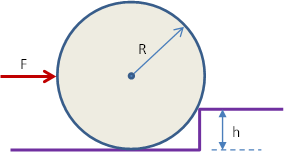
We will use Method B for the torques since that method is easiest to apply here since the location of each force can be found with the help of some geometry. We will locate the pivot at the top of the step because we have two unknowns there. The y locations of the forces, F, Mg, and Nf are easy to read from the diagram. The x location is the same for each but takes a little work as shown in the diagram below where it can be seen that x = [R2 - (R-h)2]½.
| x | y | Fx | Fy | τz = xFy - yFx |
| 0 | 0 | Nx | Ny | 0 |
| -[R2 - (R-h)2]½ | R-h | 0 | -Mg | [R2 - (R-h)2]½Mg |
| -[R2 - (R-h)2]½ | R-h | F | 0 | -(R-h)F |
| -[R2 - (R-h)2]½ | -h | 0 | Nf | -[R2 - (R-h)2]½Nf |
Since Στz = 0, the equation we get is
As pointed out, the wheel just loses contact with the ground
when Nf = 0. That gives us our expression for F,
For any applied force less than this value, the wheel remains in contact with the ground.
Questions? mike.coombes@kpu.ca
![[Return to Kwantlen Homepage]](http://www.kpu.ca/images/return_button.gif)